What is the principle and marking method of the inductor?
In the circuit schematic, the inductor is usually represented by the symbol "L" or "T". Different types of inductors usually use different symbols in the circuit schematic, as shown in Figure 1.

Figure 1 Different types of inductance symbols
The magnitude of the inductive operating capability is expressed in terms of "inductance", which indicates the ability to generate an induced electromotive force. The basic unit of inductance is Henry (H), referred to as Henry, commonly used units are millihenry (mH), microhenry (pH) and Nahen (nH). The conversion relationship between them is 1H = 102 m μH = 106 μH = 109 nH.
1 Main technical indicators of inductance
1.1 Inductance
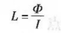
Inductance indicates the working capacity of the inductor. In the absence of a nonlinear magnetically permeable material, the magnetic flux of a current-carrying coil is proportional to the current in the coil. The proportionality constant is called the self-inductance coefficient and is represented by E, which is simply called inductance, that is:

In the formula, Φ is the magnetic flux: I is the current intensity.
1.2 inherent capacitance
In the inductor, the wire between the turns and turns has a distributed capacitance through the air, the insulating layer and the skeleton. There are also distributed capacitance between the layers of the multilayer winding and between the winding and the bottom plate. The actual circuit of the inductor can be equivalent to shown in Figure 2.

Figure 2 Inductor actual equivalent circuit
Distributed capacitance has a great influence on high-frequency signals. The smaller the distributed capacitance, the better the performance of the inductor when operating at high frequencies.
1.3 Quality Factor Q
The quality factor Q of the inductor is an important parameter of the coil quality, which represents the ratio of the inductive reactance of the coil to its equivalent DC resistance at a certain operating frequency. The Q value reflects the loss of the coil. The higher the Q value, the smaller the loss power and the higher the circuit efficiency.
1.4 rated current
The maximum current allowed to pass through the coil is called the rated current.
1.5 Loss resistance of the coil
The DC loss resistance of a coil is called the loss resistance of the coil.
2 representation of the inductance
1.1 Straight standard method
The direct standard method is to directly mark the nominal inductance (nominal value) of the inductor on the inductor body with numbers and text symbols, and the letter after the inductance unit indicates the deviation. The straight representation of the common inductance is shown in Figure 3.

