Circuit diagram inspection
1. Circuit diagram.
Circuit Diagram is a schematic diagram in which all basic components and connections of circuits, devices or complete sets of devices are represented in detail by graphical symbols and arranged in working order, regardless of their actual position. The purpose is to understand the working principle of the circuit in detail and to analyze and calculate the characteristics of the circuit.
Simply put, a circuit diagram is a pattern of circuit structure drawn with agreed symbols for research and engineering purposes. Through the circuit diagram you can know the actual circuit situation. In this way, when we analyze the circuit, we do not have to turn the object over and over, but just hold a drawing.
The motherboard circuit diagram file is now available in an electronic version of PDF, usually with 30 or 50 pages. PDF readers must be used to turn them on. You can find a wide variety of PDF readers on the Web and use them.
The circuit diagram of each motherboard is opened with the name of the factory, the description of the contents, page number, date, version and so on in the lower right corner, as shown in figure 1.

Fig.1 Circuit diagram information
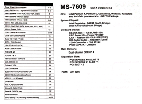
The circuit diagram page I is generally the main board drawing catalogue (see figure 2), indicating each page of the drawing and the main board chipset situation and slot number and so on. Convenient for users to view quickly.

Fig.2 Mainboard circuit diagram directory
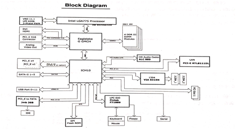
Page 2 is an architectural diagram of the motherboard that describes the connectivity and management relationships between the chips,
as shown in figure 3.

Fig.3 Motherboard circuit architecture diagram
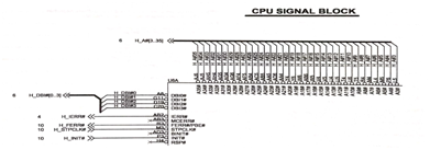
At the beginning of the third page, the circuit is divided into several parts, for example, the CPU has more circuits, one drawing can not be drawn, the CPU needs to be divided into U6A (page 3), U6B (page 4), etc. U6A represents the first page of the CPU socket, as shown in figure 4.

Fig.4 CPU socket pin distribution
This article is from Allicdata Electronics Limited. Reprinted need to indicate the source.

