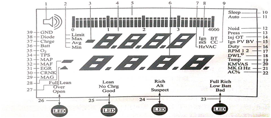
Functions of the OTC700 Series Digital Multimeter Display Panel.
The commonly used OTC700 series automobile digital multimeter display panel (take the OTC 3545 automobile digital multimeter as an example) is shown in figure 1.

The functional description that can be displayed is shown in Table 1 for reference.
Serial number | Letter code | Function description | Serial number | Letter code | Function description |
1 | Continuity | On-off test mode | 19 | Temp
| Temperature mode |
2 | Limit | Limit Settings on Small Display Panel | 20 | KMVAS | Units of measurement on large display panels
|
Max | The maximum value that can be reached on a small display panel | 21 | MkQHz | ||
Avg | Average value attainable on a small display panel | 22 | AC% | ||
Min | The minimum value that can be reached on a small display panel. | 23 | Full Rich Low Batt Bad | LED ID-engraved interface for special testing | |
3 | Negative | Negative symbols on the small display panel. | 24 | Rich Alt Suspeet | |
4 | Small Display | Display maximum, minimum and average | 25 | Lean No Chrg Good | |
5 | Bar Graph | Display current value | 26 | Full Lean Over Open | |
6 | Large Display | The unit of measure on the small display panel | 27 | Delta | Delta symbol on large display panel. |
7 | HzV AC | Small display panel intake air flow. | 28 | Negative | Delta symbol on large display panel. |
8 | Ign BT | The ignition and combustion time on the small display panel. | 29 | MAG | Negative Characters on Large Display Panel |
9 | Ms CC | 30 | CRNK | Inductor Mode of No.1 Magnetic Probe | |
10 | Sleep | Sleep patterns. | 31 | EGR | Crankshaft sensor mode |
11 | Auto | Electrically Controlled Signal | 32 | MAF | EGR sensor mode |
12 | Noid | Triggering Mode | 33 | MAP | MAF sensor mode |
13 | Press | Pressure Mode | 34 | TPS | MAP sensor mode |
14 | Inj OT | Injection timing mode | 35 | O2 | TPS Sensor Mode |
15 | Ign PV BV | Ignition peak voltage combustion voltage mode | 36 | Batt | Oxygen sensor mode |
16 | Duty | Duty cycle detection mode | 37 | Chrge | Battery detection mode |
17 | RPM12 | 1-2 stroke speed; 2-4 stroke speed | 38 | Diode | Detection Mode of Charging System |
18 | DWLO | Closed Angle Mode | 39 | GND | Diode test mode iron test |
This article is from Allicdata Electronics Limited. Reprinted need to indicate the source.

