What is the master-slave structure RS flip-flop and JK flip-flop circuit?
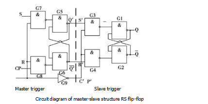
The circuit diagram of the master-slave structure RS flip-flop is shown in Figure 1, consisting of a master flip-flop and a slave flip-flop.

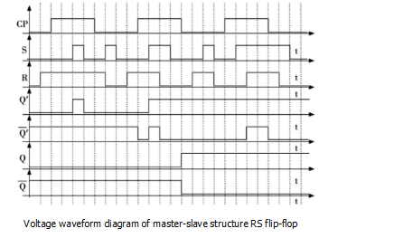
The master and slave flip-flops are composed of two synchronous RS flip-flops. According to the new sub-type RS flip-flop circuit, draw the corresponding voltage waveform diagram, the voltage waveform diagram of the master-slave RS flip-flop is shown in Figure 2 (set the initial state to 0).

When CP=1, the main trigger triggers the work, and the Q and output of the flip-flop remain unchanged. When CP=O, the trigger is triggered, and the Q’ and output of the main flip-flop remain unchanged. The change of the output state of the output occurs at the falling edge of the CP signal, but it is affected by the input signals of R and S during CP=1. In the pulse 3 of Figure 4, CP=1, when S=R=1, Q'==1, and last until the falling edge of CP, then Q'=0,=1, or Q'=1,=0 determine. Therefore, when the falling edge of the CP reaches the high level or the low level from the Q terminal of the flip-flop, the state is uncertain, and it does not mean Q, and the output level is high at the same time, which is different from the understanding of the basic RS and the synchronous RS flip-flop.
Through the analysis of the circuit, the description method of the voltage waveform change of the Q-end of the master-slave type RS flip-flop is summarized.
The slave triggers the signal according to the signal from the falling edge of the CP to the output of the main flip-flop Q' at this moment. That is, Q' = 1, =0, then Q = 1, =0; Q ' = 0, =1, then Q = 0, =1. Therefore, it is not necessary to analyze the signal of the main flip-flop Q' during CP=1. It is possible to determine Q' at the moment when the falling edge of each CP pulse comes forward. Once the signal of Q' is known, it is not necessary to know the signal of the previous Q', that is, the Q' at the moment of the falling edge of the CP. , the signal, then the CP falls along the time of arrival, the output from the trigger is also clear.
2 voltage waveform diagram
Through the analysis of the voltage waveform diagram of the trigger of different circuit structures, it is found that only understanding the characteristic table, characteristic equation and state transition diagram of the trigger is not enough. It is also necessary to understand the circuit structure to truly grasp the trigger circuit. Thus, a method of drawing a master-slave type RS flip-flop and a master-slave type JK flip-flop voltage waveform diagram is obtained.
Master-slave type RS flip-flop: Judging the change of the state of each CP's falling edge time, it is determined from the back to the front from this moment, the state of the main trigger during CP=1, once the state of the main trigger is clear Therefore, it is no longer necessary to determine the state of the main flip-flop, which is the state of the main flip-flop when the falling edge of the CP is reached, and the state of the flip-flop from the falling edge of the CP to the state of following the main flip-flop can be changed.
Master-slave JK flip-flop: judges the change of the output state of each CP falling edge, starting from the CP high level (ie, the rising edge), according to the signal change of the J and K input terminals. Determine the state of the main trigger. Once the state changes once, there is no need to analyze the subsequent input signal. Because the state of the main flip-flop can only be changed once during CP=1, this state is maintained until the falling edge of CP. The change from the state of the trigger following the master trigger.

