What is the principle of the seven-person intelligence responder?
The responder is a priority judger circuit designed for the priority of the competition for answer. The contestants can be divided into several groups. When the question is proposed, each group is asked to make a judgment in the shortest time. And press the answer button to answer the question.
When the first person presses the button, the number of the group is displayed on the display, and the circuit blocks the other groups of buttons, making it inoperative. After answering the question, the moderator will restore all the buttons and restart the next round of answering.
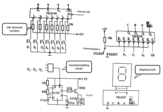
The responder should include the input switch, sound and light display, discriminant group control, and group number lock, as shown in Figure 1.

Figure 1
(1) Priority decider
The priority decider is mainly composed of 74LS148 integrated priority encoder and the like. The encoder has 8 signal inputs, 3 binary code outputs, an input enable terminal EI, an output enable terminal EO and a priority coded operational status flag GS. When EI=“0”, the encoder works,.
When EI=“1”, the output is “1” regardless of the state of the 8 pcs input terminal, and the GS and EO are “1”,the encoder is inactive . This condition is called low level is valid.
When one of the answer switches S1~S7 is pressed, the encoder outputs the corresponding code corresponding to the corresponding button, and the low level is valid. The encoder outputs A0~A2, the working state flag GS as the input signal of the latch circuit, and the input enable terminal E should be connected to the Q0 terminal of the latch circuit for the purpose of "1" at the EI terminal. Lock the encoder's input circuitry so that other input switches do not work.
(2) Latch circuit
The latch circuit can be composed of four R-S latches 74LS279. The 74LS279 is a latch circuit consisting of four basic R-S flip-flops. The R terminal is connect to the "0" terminal, and the S terminal is connect to the "1" terminal. Normally, the input terminal is at a high level and the flip-flop is held status.
In the latch, the R terminal is connected to the host's switch. Before answering, the control switch makes the latch output zero. S1, S2, S3, S4 are respectively connected with the output end of the encoder into A2, A1, A0 and the working state flag GS. When the answering switch is pressed, the encoder outputs the corresponding binary code and keeps the answering information through the latch.
The encoder working state flag GS makes the latch output Q0 ="1", Q0 is connected to the input enable terminal EI of the encoder 74LS148, blocks other input, and is connected to the control terminal BI/RBO of the decoding circuit 74LS247, when When it is high, the decoder works. When it is low, the glyphs are all "off". Q1, Q2, Q3 are connected to the input end of the decoding display circuit, the control switch is set by the moderator, and the next round of acknowledgment can be performed after the S is reset to the RESET terminal.
(3) sound prompt circuit
The sound prompting circuit can adopt a multi-vibrator composed of 555 integrated timers, and the output end is amplified by a triode to push a buzzer. When someone presses the answering switch, the digital display is accompanied by an audible prompt to remind the host to note.
This article is from Allicdata Electronics Limited. Reprinted need to indicate the source.

