What is the relationship between the circuit structure and the logic function of the trigger?
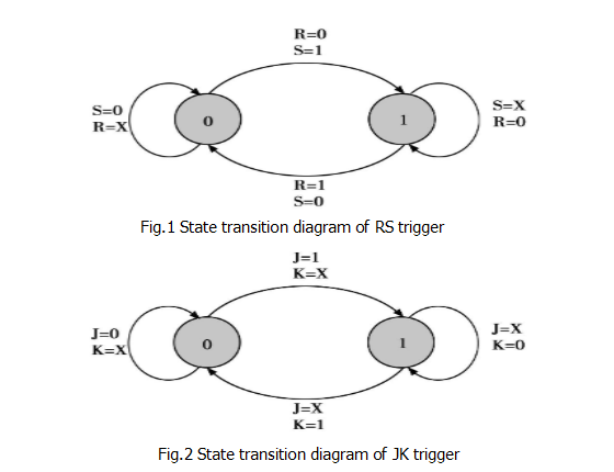
With the continuous expansion of digital integrated circuits and the enhancement of functions, digital electronic technology is becoming more important as a basic course of professional technology. The description of the trigger has a characteristic table, a characteristic equation, and a state transition diagram, and the voltage waveform diagram of the trigger is both important and difficult. For example, a basic RS trigger. What is the difference between the indeterminate state of the synchronous RS flip-flop and the indeterminate state of the master-slave type RS flip-flop , and the characteristics of the master-slave type RS flip-flop and the master-slave type JK . The RS and JK flip-flops are analyzed from the voltage waveform diagram below. The state transition diagram of the RS flip-flop is shown in Figure 1. The state transition diagram of the JK flip-flop is shown in Figure 2.

The relationship between the circuit structure and logic function of the flip-flop
First, the circuit structure is different, and the action characteristics are different.
Classification: Basic TS Trigger, Synchronous RS Trigger, Master-Slave Trigger, Edge Trigger, etc.
Second, the logic function refers to the logic relationship between the secondary state of the trigger and the current state and the input signal in the steady state.
It can be represented by a property table, a characteristic equation, or a state transition diagram.
Classification: RS trigger, JK trigger, D flip-flop, T flip-flop, T/flip-flop, etc.
Third, the logic function is the same and the circuit structure is different, the action characteristics are different when the state is reversed.
Fourth, the trigger of the same logic function can be realized by different circuit structures;
The same circuit structure can be used as a trigger for different logic functions.
That is: there is no fixed correspondence between the logic function and the circuit structure.
5. The JK trigger contains all the logic functions of the RS trigger and the T flip-flop.
At present, there are only two types of clock control trigger shaping products: JK flip-flops and D flip-flops.
JK trigger
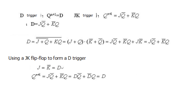
1. Let J=S, K=R and J and K are different at 1 and the constraint condition SR=0, which constitutes an RS flip-flop.
2. Let J=K=T be the T flip-flop.
Using a D flip-flop to form a JK flip-flop

RS flip-flop circuit analysis
The characteristics of the RS flip-flop are known from the characteristic table and the state transition diagram. When S=R=1, the states are all indeterminate, and the triggers of different circuit structures have different action characteristics.
1.1 Basic RS Trigger
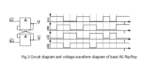
The circuit diagram and voltage waveform diagram of the basic RS flip-flop are shown in Figure 3.

According to the analysis of the basic RS flip-flop circuit, when SD=RD=0, Q is high level, and SD and RD become high level at the same time, Q and output are O, 1 (or 1 , 0) cannot be determined. That is to say, when SD=RD=0, the state of Q and output is determined, that is, the state is indeterminate. When SD and RD change from 0 to 1, the state of Q and output is uncertain (Q= 1, = 0, or Q = 0, = 1, not sure).
1.2 Synchronous RS Trigger
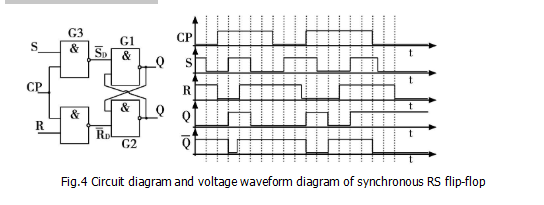
The circuit diagram and voltage waveform diagram of the synchronous RS flip-flop are shown in Figure 4.

According to the analysis of the synchronous RS flip-flop circuit, when CP=0, S=X, R=X, Q and output remain unchanged; when CP=1, the working condition is the same as the basic RS trigger (set Q) The initial state is 0).
During CP=1, S=R=1, Q and output are high level at the same time. Once CP changes from high level to low level, the state of Q and output is also indefinite (ie, Q=0,= 1, it is also possible that Q = 1, =0). Its output state is random and cannot be determined.
If you want to know more, our website has product specifications for the triggers, you can go to ALLICDATA ELECTRONICS LIMITED to get more information

