What is the working principle of the bias circuit in the triode amplifier circuit?
Amplifying circuits are widely available in electrical and electronic circuits, so it is necessary to master the basics of amplifying circuits.
Amplifying circuits, also known as amplifiers, are one of the most widely used electronic circuits and the basic unit circuits that make up other electronic circuits. The so-called amplification is to amplify the input weak signal (referred to as the signal, refers to the changed voltage, current, etc.) to the required amplitude value and consistent with the original input signal variation law, that is, to perform distortion-free amplification. It only makes sense to zoom in without distortion. The essence of the amplifier circuit is the control and conversion of energy. According to the common end of the input loop and the output loop, the amplifier circuit has three basic forms: a common-emitter amplifier circuit, a common-amplifier circuit, and a common-base amplifier circuit.
The actual amplifying circuit is usually composed of a signal source, an amplifier composed of a transistor, and a load.

Current negative feedback bias circuit
In the amplifying circuit, a current negative feedback bias circuit is usually used. This paper mainly explains the stable working principle of the bias circuit.
Component introduction
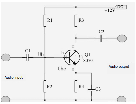
b: the base of the triode. Ib: Transistor base current. c: Transistor collector. Ic: Transistor collector current. e: Transistor emitter. Ie: Transistor emitter current. Ub: Transistor base voltage. Ube: Transistor base emitter voltage.
R1, R2: called the base voltage divider resistor, which provides the base current for the circuit core amplifier transistor. When the base current (Ib) changes, Ub (the voltage across R2) remains substantially unchanged.
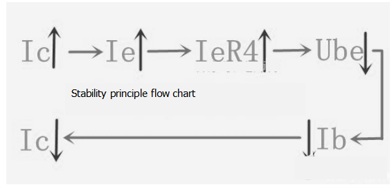
R4: Called the emitter resistor, also known as the stabilizing resistor, also known as the feedback resistor, the key components of the amplifier circuit! The function is to stabilize the DC operating point. When the triode amplifier circuit is due to temperature rise and other factors, the collector current (Ic) is kept stable. The stability principle is as follows:
The principle of stable operation of the amplifier circuit

Stability principle flow chart
1: As the temperature rises, the collector Ic increases, the emitter current Ie increases, and the voltage IeR4 across R4 increases. Ub is provided by the voltage dividing resistor, Ub remains basically unchanged, because Ube=Ub-IeR4, Ube It will decrease, the corresponding base current Ib will decrease, and the increase of the collector Ic will be suppressed, thereby stabilizing the collector current DC operating point, thereby reducing the adverse effect of temperature rise on the circuit.
2: R4 feedback resistance amplifier circuit key components, appropriate increase R4 resistance value, the greater the feedback, the stability is good. Therefore, it is necessary to make a reasonable choice according to the actual circuit design. In order to reduce the loss of AC energy on R4, the C3 capacitor is added to bypass the AC to the ground, and the AC gain of the amplifier circuit can be improved.
3: The current negative feedback bias circuit has good temperature stability. As long as the proper bias resistance is selected and a reasonable DC operating point is designed, the amplifier circuit can work stably and reliably. Therefore, it is a bias circuit that is widely used in an amplifying circuit.
If you want to know more, our website has product specifications for the triode amplifier, you can go to ALLICDATA ELECTRONICS LIMITED to get more information

