What is the working principle of water tank water level automatic controller ?
In some areas, well water is commonly used in daily life water. For the convenience of use, a water tank is often installed on the roof, and the well water is pumped to the roof tank through a water pump, and the water in the water tank is usually used to achieve the same as tap water convenient effect.
In use, it is often found that there is no water in the water tank after the water in the water tank is used up.
At this time, the water pump power supply is turned on to supply water to the water tank. The whole process requires manual participation, which is very troublesome.In addition, sometimes the water in the water tank overflows due to negligence, making the entire roof full of water
Now introduces the working principle of a water tank automatic level controller circuit which can automatically start the pump pumping when the water level in the water tank is lower than the predetermined water level:
when the water level in the water tank reaches the predetermined high water level, the water pump stops pumping and keeps the water tank is a certain amount of water, which will neither dry nor overflow. It is very practical and convenient.
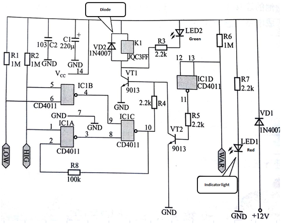
The circuit adopts CMOS circuit CD4011 (including four NAND gates circuit) as the processing chip, and the water tank automatic controller schematic diagram, as shown in Figure 1.

Figure 1 Schematic diagram of the water tank automatic controller
After the DC voltage DC 12V is stepped down by the diode VD1, the current through R7 causes LED1 to illuminate as a power indicator. and the other current serves as the operating power of the system.
After the power is turned on, if there is no water in the water tank, the two water level probes are connected to the positive power supply via R1 and R2, which is high potential. The 4 pin of IC1 output low level. After IC1C processing, the 10 pin output high level. This high-level path is added to the base of VT1 via R4, so that VT1 is saturated, the relay is energized, and the pump is pumped.The other is connected to the 2 pin of IC1 via R8, because the high-water probe is also high level, after the NAND gate circuit processing, IC1's 3-pin output is low, and the IC1C is locked with the NOT gate.
As the water pump continuously supplies water to the water tank, the water level in the water tank gradually rises. When the low water level probe is immersed in water, the 6 pin of IC1 become low level, and the 4 pin output high level, but at this time the NAND gate circuit has been locked, so it will not affect the output, the pump continues to pump water.
As the water level rises further, when the water level hits the high water level probe, the 1st and 6th pins of IC1 become low level. This change has no effect on the 4th pin of IC1, but the 3rd pin is changed by 1 pin. Low level, the output is high level, so ICI's 8 and 9 pin are high level, 10 pin will output low level, the relay will lose power, the pump will stop pumping, and this low level will pass R8 add to pin 2 to keep pin 3 high level.
Until the water level is again lower than the low water level probe, the foregoing process will be repeated to automatically control the water level of the water tank. The circuit is designed with a fault protection circuit. When the high water level probe fails due to electrode oxidation, the stop signal cannot be issued. At this time, the water level continues to rise. When the WAR end probe is immersed in water, the pump will be forced to stop use as protection.
This article is from Allicdata Electronics Limited. Reprinted need to indicate the source.

