A method of detecting gas-sensitive resistors by using pointer multimeter current shields.
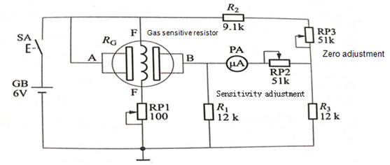
Judging whether or not the gas resistor is good or not can be detected by connecting the gas sensitive resistor detection circuit according to the circuit diagram shown in fig. 1. The uA in the diagram is the corresponding current block of the pointer multimeter.

Figure 1
The first is the description of the detection circuit.
In figure 1, the gas resistor Rc and the related resistor form a bridge circuit, the bridge. Each arm is a sensitive layer resistor, the adjacent arm consists of a bridge balancing zero adjustment potentiometer RP3 and resistor R, and the other two arms are resistor R and R3 respectively. The bridge detection part is composed of an indicator-type multimeter micro-safety PA and a sensitivity-adjusting potentiometer RP2. RP1 is a heater voltage regulating potentiometer with a heating voltage of 4.5 V. The heating voltage should usually be selected according to the actual requirements for the measured gas resistor.
Second, the detection method.
When the balance of the bridge is adjusted, the corresponding gas is applied to the gas sensitive resistor. If the indication of the PA meter changes, the measured gas sensitive resistor is good, otherwise it is bad or damaged.
If you want to know more, our website has product specifications for gas-sensitive resistors, you can go to ALLICDATA ELECTRONICS LIMITED to get more information

