Different roles of different resistors in the circuit
1.Protective resistor.
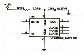
The function of the protective resistor is to protect the main components of the circuit from burning out. In figure 1, R295 is used to protect the resistor. When the chip U25 is overloaded or short-circuited, the current through the resistor R295 becomes larger. When the resistance is beyond the range that the resistor can withstand, the resistance spontaneous combustion causes the circuit to be open and the chip power supply is disconnected. Thus protecting the front 12 V main power supply circuit from being damaged. The protective resistor is generally below 10 Ω.

Fig.1 Protective resistor application circuit
2. Pull up resistor.
The role of the pull up resistor is to pull the uncertain signal to a high level to increase the signal current, so that the signal can be transmitted at long distance and at high speed. In figure 2, the RN3 is a pull-up resistor. The LDT_RST# signal is pulled up through the RN3 to the VCC_DDR voltage to increase the working current, and the pull-up resistor also acts as a finite current.
3. Pull down resistor.
The pull-down resistor is used to set the working state of the signal by grounding the uncertain signal through the resistor. Figure 3 the PGNT#0 signal is grounded through the pull-down resistor R608, setting the PGNT#0 signal to a low level state. The pull-down resistor on the signal line absorbs the current, absorbs the current of the output signal to the GND, and reduces the impact of the signal on the back stage circuit.

Fig.2 Pull up resistor Fig.3 Pull-down resistor
application circuit application circuit
4. Partial voltage resistor.
The circuit with both pull up resistor and pull-down resistor is called divider circuit. A suitable voltage can be obtained by a normal power supply. Divider resistors are used in power supply circuits or reference voltage circuits with low current. The R424 and R423 in figure 4 form a voltage divider circuit. The R424 connection power supply is called the upper resistor, the R423 grounding is called the lower resistance. After the 1_5VREF voltage is divided by R424 and R423, the DDR3_1_5REF voltage is obtained as the reference voltage to the memory.
5. The resistance is judged.
The method of measuring the resistor is shown in figure 5. The digital multimeter is adjusted to the ohmic block, the two multimeter pens contact the two ends of the resistor, and the value of the measured resistance is displayed on the display screen. If the measured value does not match the resistor indicator, the measured resistor is damaged.

Fig.4 Resistive partial voltage application circuit Fig.5 Resistance measurement
Note that:
(I) resistor damage is generally shown as a larger resistance or open circuit.
(2) because of the different materials of the resistor, the resistance value will have certain error, the resistance within the error range of the measurement value belongs to the good resistor.
(3) when accurate measurement is needed, the resistor must be removed and measured.
Allicdata Electronic specialize in the production of resistors includes chassis mount resistors,through hole resistors,resistor networks,arrays,etc. If you are sourcing the products, please contact us, we will try our best to solve it for you. For more product information, please go to the website to get it.

