What are the practical effects of Hall effect sensors?
Practical considerations
High-quality sensors provide high accuracy, excellent linearity, and low temperature coefficients. Suitable probes for specific measurements and instruments are usually available, and the manufacturer provides certified calibration data.
Some of the more important practical considerations for instrument-level Hall-effect sensors are:
Precision. The designer must determine the accuracy required for a particular measurement. It can achieve reading accuracy of 1.0% to 2.0% without signal conditioning. In many applications, 0.4% accuracy can be achieved using a microprocessor calibration.
angle. As mentioned earlier, the Hall sensor output is a sine function of the angle θ between the Hall plate and the magnetic field vector. When the magnetic field vector is perpendicular to the device plane (sin90 ° = 1.0), the output reaches the maximum value, and when the magnetic field vector is equal to the sensor plane, the output is the minimum value (close to 0). The manufacturer calibrates the Hall sensor at its maximum output, so the angle error of the test fixture or probe needs to be considered.
temperature. Many sensor solutions can support a wide range of temperature and magnetic fields.
Instrument-grade sensors support a temperature range from 1.5K (-271 ° C) to 448K (+ 175 ° C) and a magnetic field range from 0.1 Gauss to 300,000 Gauss. Hall sensors have two temperature coefficients: one is the temperature coefficient used for magnetic field sensitivity (calibration), and the other is related to deviation (zero) changes. The effect of temperature on calibration is a percentage of the reading error, and the zero effect is a fixed magnetic field value error that depends on temperature.
Deviation variations are even more important at low magnetic field readings (less than 100 Gauss). The technician should carefully study the two temperature coefficient specifications given by the manufacturer, and then determine whether a particular application can maintain the desired accuracy within the target temperature range.
Input current limit. Designers are advised to know the required input current value and take care not to exceed the specified maximum. Remember that under normal circumstances the Hall effect device is calibrated at a certain current value. Any change from the calibration current will change the output of the sensor. However, this is also an available feature. As long as the maximum current value is not exceeded, the current doubled output will also double.
As mentioned earlier, the basic instrument-level Hall sensor is a piece of low-resistance material with 4 electrical contacts. The input and output circuits are not isolated from each other, so you must avoid using common connections in the input and output circuits. To meet this requirement, you can use an isolated current source or a differential input amplifier for the output.
Sensor installation alternative
In some measurement applications, the use of standard probes is impractical or undesirable. Instead, Hall-effect sensors are mounted directly on mechanical components. Customized sensor mounting design is beyond the scope of this article. Here are some general guidelines that are useful in custom mode:
Fragile. Hall sensors are particularly fragile and can be easily damaged by bending stress. Therefore, avoid contact between the Hall plate and the surface or device that exerts direct pressure. In some applications, a non-conductive ceramic or other insulating material is used as the interface sheet.
Binding. The binding adhesive must be carefully selected so as not to stress the sensor. When the temperature change does not exceed room temperature ± 10 ° C, ordinary epoxy (such as 5 minutes air-drying type) is fine. Sealing is generally not recommended, except in highly corrosive environmental conditions. Other bonding methods can also be used to reduce the stress on the sensor leads, such as binding them to a mounting substrate.
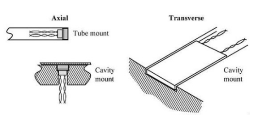
Machining cavity. These cavities can be used for axial or lateral Hall sensors, with the sensor top recessed under the surface to help prevent pressure contact or wear.
Test tube installation. The test tube mounting method (Figure 1) can be used to protect the axial Hall sensor.
The recommended method is to choose the most robust sensor for any custom installation application. Units packaged with ceramic or phenol are generally the most durable.

Figure 1: The axial sensor can be installed in a test tube, where the sensor can be exposed or recessed in the cavity to be protected. Transverse sensors are generally installed in recesses.
Integrated proximity and rotation sensors
Hall-effect sensors have been widely used in various linear proximity detection devices to respond to changes in the magnetic field of the proximity device. For example, the detected magnetic pole may be close to the sensor perpendicular to the Hall plate, or the magnet passes through the plane of the sensor. This movement will cause the generated voltage to change. Additional integrated circuits convert Hall voltages into significantly larger digitally compatible signals.
Angle detection, rotation, and speed detection use the same Hall effect principle to test repetitive physical changes in position. For rotation, speed or angle sensors, the magnetic pole is connected to a rotating object, such as a motor shaft, and the Hall plate is stationary. Well-known angular coordinate applications include detecting commutation of brushless DC motors and rotation angles of engine crankshafts.
Each type of device used for proximity, rotation, and current detection is some form of Hall-effect "switch" that is triggered by the Hall-effect output and then fed into other integrated electronic circuits. This switch provides a binary high and low output based on the detected magnetic field value or the most recent magnetic field value and polarity. When combined with a current-carrying coil, a Hall-effect switch can also provide current detection for an overcurrent circuit breaker.
If you want to know more, our website has product specifications for Hall effect sensors, you can go to ALLICDATA ELECTRONICS LIMITED to get more information

