How to choose the drive resistance in the triode analog circuit?
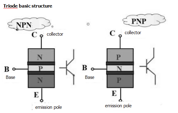
The triode is a current control device that can be used as a non-contact switch. It is often used in switching circuits to control the conduction and disconnection of the triode through input signals, thereby turning the circuit on and off. The triode has three electrodes: emission Pole (E), collector (C), base (B). According to the combination of PN junctions, the triode is divided into PNP type and NPN type. According to the intrinsic semiconductor material, there are silicon tubes and manifolds.
The triode has three working states: cut-off, linear amplification, and saturation. As a switching function, the triode operates in a cut-off and saturation state, corresponding to the opening and closing of the switch.

1) Cut-off state: When the base bias voltage of the triode is smaller than the turn-on voltage of the PN junction, when the base current Ib=0, the collector Ic and the emitter Ie have no current (or only a weak weak current), and the triode Losing the current amplification, we call the triode working in the off state, and the CE pole is equivalent to the disconnection state of the switch.
2) Saturated state: When the base bias voltage of the triode is greater than the turn-on voltage of the PN junction, and the base current increases to a certain value, the collector current Ic does not substantially change with the change of the base current Ib, and It is close to a certain value, and this phenomenon is called saturation. At this time, the triode loses current amplification, the voltage between the collector and the emitter is small, and the triode is in an on state, which is equivalent to the conduction state of the switch.
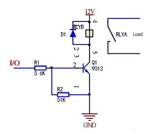
Transistor 9013 drives a 12VDC electromagnetic relay circuit, 9013 which is a low voltage, high current, small signal NPN type silicon triode. The triode control relay uses the off-state and saturation state of the triode. When the triode is in saturation, we always want the Vce voltage to be as small as possible. Take the RWG1-DC12V-ZS type relay as an example.

When the relay is turned on, the 12V voltage is basically dropped on the coil. The typical coil resistance of the 12V relay is 400Ω. Then the current flowing through the coil is the current of the transistor Ic when it is turned on. At this time, Ic=12/400=30mA. If the collector Ic=30mA at this time, look at the 9013 specification to find the Ic-Vce relationship graph, and the current flowing through the base B can be about 180uA, and the resistance value R of the series connected to the base B can be further determined. = (5V-0.7V) / 180uA ≈ 23.8K, so theoretically 20K of resistance can be.
However, in practice, the level of the voltage is different. For TTL level and CMOS level, the transistor turn-on voltage may be greater than 0.7V. The difference in resistance may not be as large as 20K. Therefore, in order to make the circuit more reliable, it is generally preferable to take the current flowing through the CE pole to be 2-3 times of the design value, then, according to the calculation of 2 times, that is, 60 mA, at this time, for the current flowing through the base B 360uA, further Find the base resistance of 11.9K, so we often use 10K resistors to drive the triode, and lower ones can also take such frequently seen resistors as 8.2K, 5.6K, 5.1K.
If you want to know more, our website has product specifications for the drive resistance, you can go to ALLICDATA ELECTRONICS LIMITED to get more information

