How to make an electronic energy saving lamp?
l Principle
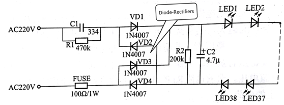
The electronic energy-saving lamp produced in this example uses 38 pcs high-brightness LEDs as the light source, and is powered by the household voltage through the resistance-reducing step-down voltage. It has the characteristics of simple circuit principle, few component types, and convenient installation, and is very suitable for electronic beginners.
The lamp head is designed with standard screw (E27). It can be directly connected with the household screw socket (E27 lamp holder). The good electronic energy-saving lamp can be used as household lighting, The electric power of 3.5W is equivalent to the brightness of a 40W incandescent lamp, and the energy saving effect is remarkable. The schematic diagram of the circuit is shown in Figure 1.

Figure 1
l Circuit production
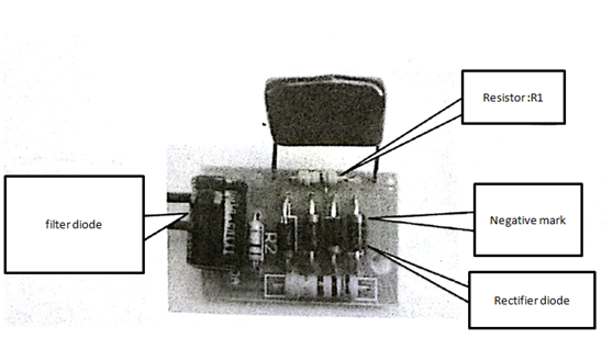
Pay attention to the direction of the positive and negative polarity of the diode when installing the rectifier diode.
The horizontal line corresponds to the horizontal line on the diode. The bleeder resistor R1 is mounted under the step-down capacitor. After soldering, the C1 is mounted. The step-down capacitor is mounted horizontally. The position is placed above the rectifier diode. Good pin, otherwise the pin will not bend once the pin is cut too short, as shown in Figure 2.

Figure 2 Installing the power board
When installing the light-emitting tube (LED), pay attention to the symbol mark on the circuit board. The missing corner of the arc corresponds to the missing corner on the light-emitting tube. When welding, first weld the tube at the center, cut the foot after welding, and then weld the outer ring diode, otherwise the outer ring diode pin will block the welding of the inside diode.
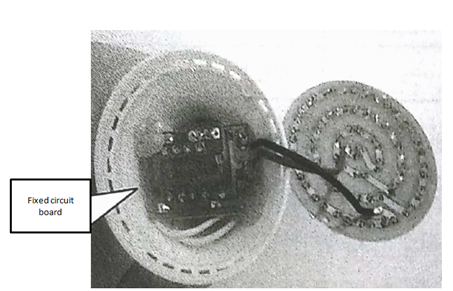
When the power board is installed in the lamp holder, the components face down, and after placing well, the plastic are melted on the opposite corners of the circuit board by the soldering iron, and the fixed the board are not moved until the plastic are cooled and shaped.

Figure 3 Fixed circuit board
Put the light board in the light cup, install the light cover, and the LED light will be done.
Note: After all components are installed, they should be carefully checked to confirm that the components are installed correctly. Then the power supply can be detected. This example uses 220V power supply. Do not touch any conductive parts with your hands during debugging. If there are conditions, you can use the isolation transformer for debugging. If you do not have the E27 lamp holder to fix the tool, please purchase the lamp housing with the lamp holder fixed.
Related articles:
What is an capacitor and how to distinguish the inductance value?
What are the characteristics and applications of white LEDs?

