How to make a fast battery charger?
1. This article introduces a small fast charger that can charge two No. 5 or No. 7 rechargeable batteries at the same time. It is equipped with a charging indicator to indicate the charging status. When the battery is low, the indicator light is brighter. As the power is continuously replenished, the brightness of the indicator light keeps decreasing. When the charging is completed, the indicator light goes out. The charger has an automatic adjustment function of first charging with a large current and then charging with a small current, and has a good protection effect on the rechargeable battery.
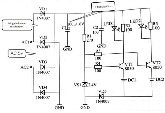
The schematic diagram of the charger is shown in Figure 1. The AC 220V is stepped down from the AC1 and AC2 terminals after being stepped down to AC 5V by the power transformer. The bridge full-wave rectification is formed via VD1 ~ VD4. After filtering by the capacitor, it supply the charger with power. The power supply provides the base current to the three charging switch transistors via the resistor R1. The voltage regulator VS1 always maintains the base voltage of the two transistors at about 2.4V. When the rechargeable battery is connected, the charging circuit is turned on. Taking DC1 as an example, since the emitter voltage of the transistor VT1 is determined by the voltage of the battery, the base voltage is kept at a stable value. When the battery voltage is low, the voltage applied to the emitter junction of the transistor VT1 is large, and the collector is charged. The current is large and the brightness of the LED is also large. As the battery power is continuously replenished, the battery voltage is continuously increased, and the voltage applied to the triode VTI emitter junction is continuously decreased, and the charging current is continuously reduced. When the current is sufficient, the emitter potential of the triode VT1 is higher than the base potential. The triode VT1 is turned off, the charging is over, and the charging indicator is off. At this time, even if you forget to remove the battery, the rechargeable battery will not be damaged due to overcharging. The charging condition of DC2 is basically the same as the foregoing process, so the charger has the function of automatically adjusting the charging current according to the battery power during the entire charging process.

Figure 1 charger schematic
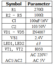
2. The device parameters are as follows:

3. Circuit production
1) When installing the diode and the triode, be sure to pay attention to the polarity and do not insert it in the reverse direction, strictly according to the marking on the circuit board or silkprint.
2) The ceramic capacitor and the resistor have no direction, so just install it according to the specific position.
3) Pay attention to the polarity when installing the electrolytic capacitor. Before the cutting pin, among the two pins of the electrolytic capacitor, the long one is positive and the short one is negative, so pay special attention during installation.
4) When installing the positive electrode of the battery, first put the tin on it, and also put the tin on the circuit board. The direction of installation is opposite to other components. The protruding part should be on the welding surface of the circuit board. Due to the large area of the device during soldering, Be careful not to get hot. In actual installation, it is best to clamp the metal part with pliers to position it, and then solder it. Since the metal part is large in area and fast in heat dissipation, it is better to use 60W soldering iron for welding if conditions permit. It is not easy to damage the circuit.
5) For several higher components, all installations are horizontally mounted, otherwise the components will bump against the casing.
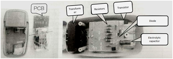
After the components are all installed, as shown in Figure 2.

Figure 2
4.Commissioning instructions
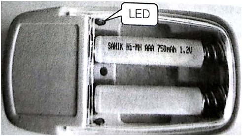
As long as the installation is correct, it can be successfully completed. Turn on the power and measure the voltage across VS1. When it is normal, it is 2.4V. Take a 7-cell rechargeable battery with insufficient power and put it into the charging stand to see the charging indication. The light is brighter. After more than one hour of fast charging, the brightness of the indicator light will continue to decrease. The specific time varies depending on the performance of the battery. Until the end, the charging indicator will go out. At this time, the battery is removed for measurement. The voltage should not be lower than 1.3V. The charger making kit has strong practicability, and the fast charger as a household battery has a high cost performance, and the appearance of the actual installed charger is shown in figure 3.

Figure 3 charger appearance
This article is from Allicdata Electronics Limited. Reprinted need to indicate the source.

