How to make an water tank water level automatic controller production?
The automatic water level controller of the water tank can automatically start the pump pumping when the water level in the water tank is lower than the predetermined water level。When the water level in the water tank reaches a predetermined high water level, the water pump stops pumping, and the water tank always has a certain amount of water. It will neither dry nor overflow, very practical and convenient.
According to the working principle of the water tank automatic controller (article link: https://www.allicdata.com/article-845.html ), it can be made as follows:
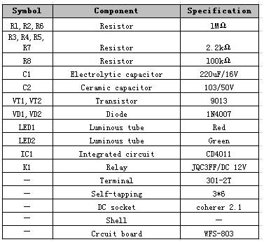
1. Water tank water level automatic controller component list

2. Commissioning and installation
The welding procedure is as follows:
1) Power section
The diode and related components are soldered to the marked position on the board. When the LED is soldered, the power section can be debugged. Plug in the regulated power supply from the power input to see if the LED is lit. If it is not lit, check if VD1 is soldered.
2) Output section
After the power supply is normal, the relay and output transistor are next soldered. After soldering, power on again, use a wire to touch the positive power supply and IC10's 10-pin position (the integrated circuit is not soldered at this time).
If you can hear a crisp sound from relay , and can see the indicator light is on.Another sound can be heard after disconnection of relay, and the work indicator is off, indicating that the output part is also correct.
3) Processing part
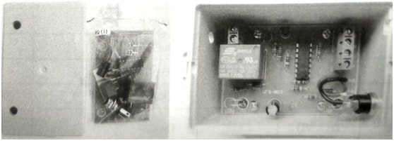
After the previous two parts of the test project is normal, as long as the IC and related resistors are soldered, it will work. The installation position of the water level controller after the completion of the production is shown in Figure 1.

Figure 1 water level controller
Commissioning: Connect the wires to the terminals on the circuit board, connect the power supply, the power indicator lights up, and the relay should be closed. Then connect the lead of the low water probe to GND by hand, and then connect the high water level probe with When GND is connected, the relay is disconnected; then the high water level probe lead wire is disconnected from GND, and then the low water level probe lead wire is disconnected from GND.
At this time, the relay is again sucked and tested several times. The above changes in the rules indicate that the circuit is working properly. During the test, a disposable cup can be used to put the water line into the cup according to the height and then add water to the cup to simulate the whole pumping process. In actual installation, the water level probe is made of stainless steel tube of φ16 ~ 20mm, which is not easy to rust and has good reliability. Insulate the probe into the water tank and the tank cover. The installation can be done with a waterproof joint. The stainless steel tube is inserted into the middle and tightened. The stainless steel tube of φ16~20mm is equipped with the waterproof joint of PG21 or PG29.
Use a two-core shielded cable as the water-level signal lead-in, connect the shield to the tank casing, and connect the other end to the GND of the board. The two cores are connected to L and H on the board, where L and low water. The probes are connected and H is connected to the high water level probe. Note that the water level signal line should be as short as possible. If it is too long, it may be subject to external interference, making the system unable to work properly. Finally, the lead wire for controlling the pump power supply is connected to the output terminal of the relay, and the system is installed. The wiring diagram is shown in Figure 2.

Figure 2 Wiring diagram of the water level probe and controller
The wiring of the water level probe and the controller is as shown in Figure 2. The four probes are connected to the terminals corresponding to the water level terminals on the controller through the connection. The probe line should not be too long, preferably within 1.5m. If it is too long, it is easy to introduce radio interference signals, and the system will not work properly.
This article is from Allicdata Electronics Limited. Reprinted need to indicate the source.

