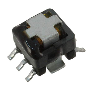
What is the difference between a transformer and a coupled inductor?
Two inductors coupled together can be defined as separate components that share some of their flux lines. Due to the common coupling, one winding induces a voltage in the other winding: this is called mutual coupling.
Transformers, which are actually intended as "transfer" and signal impedance matching components, even nowadays certainly apply to the energy used in the sense of "conversion", ie the transfer of voltage and current.
The two components - the coupled inductor and the transformer - are very similar on the surface. However, their parameters are optimized differently, and because of the difference between the named coupled inductor and the transformer, it is necessary to clarify the different uses.
Of course, in the end only the data table shows which parameters the component has and where they can be used. The transformer is specifically designed to transfer power from one winding to another. The coupling between the two windings must be as good as possible and the leakage inductance is close to zero. For this type of application, the absolute inductance of a single winding is usually secondary.
The transformer transfers energy directly from the primary winding to the secondary winding without storing energy in the magnetic circuit. For this purpose, current flows simultaneously in both windings, their magnetic fluxes being oppositely polarized and canceling each other out. Standard transformers are usually designed with fixed coupling to achieve values above 99%.
Typically transformers are used for power transmission where reduced coupling results in losses and inefficiencies. Coupled inductors have different strength couplings, from very low couplings, typically only 5% to 10% to over 90%.
In a transformer, an AC voltage is typically applied to the primary winding to generate a voltage on the secondary side, and power transfer occurs here immediately. Any portion of energy stored is often considered a problem because it can cause damage. Most transformers are wound on the core with low reluctance. Although the core has magnetization and leakage inductance, these are caused by parasitic effects.
An ideal transformer does not have these parasitic properties; an ideal transformer cannot store energy. The coupled inductor can store energy in accordance with an embodiment. The inductor is then designed to store considerable energy in the magnetic flux.
For this reason, the core has gaps, discrete gaps or distributed, such as iron powder cores, where the energy is stored as a magnetic field. Furthermore, the ferrite material and the winding structure are suitable for the corresponding type of coupled inductor.
For coupled inductors, each winding is still used alone as the actual inductor, although "some mutual coupling" of course acts as a circuit technology, there will be two separate inductors. Generally, stray inductance is not a problem for coupled inductors.
In fact, it may be useful to provide some guaranteed, low, uncoupled inductance or leakage inductance for each winding. The absolute inductance of each winding when the secondary winding is turned on is a precisely defined important parameter. Most of these coupled inductors have the same number of turns - a 1:1 gear ratio, but some special types have a higher gear ratio of 1:50 or higher.
The mutual coupling of a coupled inductor of the magnetic circuit at the magnetic flux produced by the windings is of the same polarity and is interesting such that, in addition, this results in a non-negligible value of the magnetic flux and magnetic energy is stored at the core.
Applications for coupled inductors typically include the use of separate inductor circuits, but one of the two coupling functions between the two inductor circuits facilitates the function of one or more circuit parameters. A coupled inductor can be used, for example, in a flyback converter where it stores energy while the switching transistor (MOSFET) is turned on and then transfers energy to the output when the switching transistor (MOSFET) is turned off.
Coupled inductors have many other advantages, such as significantly reduced current ripple, voltage conversion, changing circuit impedance, and galvanic isolation. For example, switching power supplies include SEPIC converters, galvanically isolated converters, multiphase converters, and special converter circuits that mitigate the negative characteristics of hard switching.
However, coupled inductors also have disadvantages, which result in inductors having, for example, slightly higher losses and non-ideal operations in the flyback converter, such as round, rather than causing triangular waveforms that must be considered in the circuit. In addition, the current specifications of the coupled inductor differ depending on whether their windings are connected in series or in parallel.
For example, when the windings are connected in series, the equivalent inductance due to mutual inductance is greater than twice the rated inductance. Unless otherwise specified in the data sheet, the saturation and RMS current ratings must be applied to both current flowing through the two windings. Therefore, a clear understanding of the operation and specifications of coupled inductors is critical to making the most of these devices.


