What is the working principle of various buck regulators?
One of the most common switching regulator topologies is a step-down switching regulator. Buck regulator ICs usually use a built-in controller and integrated FET for buck conversion. Not only that, the buck regulator IC can also be applied to various designs, such as inverting power supplies, bipolar power supplies, and isolated power supplies with single or multiple independent voltage outputs. This article introduces the design of various buck regulators, explains how they work, and discusses the practical factors that need to be considered to implement these designs.
Bipolar power supply using buck regulator IC
Many applications, such as operational amplifiers and data acquisition systems, require a bipolar ± 5V or ± 12V power supply. A common approach is to use a single switching regulator and coupled inductor (also commonly referred to as a transformer) to produce negative and positive voltage output. Figure 4 shows how to use a buck converter and an inverting buck-boost converter to generate a bipolar power supply.
As shown in (a), first configure the ISL85410 buck regulator as a buck regulator to regulate the positive output VOUT +, and then generate a negative output VOUT- by adding additional coupling windings. If the positive output VOUT + is adjusted as in a buck converter, the negative output VOUT- has the same value as VOUT + (for simplicity, the forward voltage drop of the rectifier diode D1 is ignored), but with opposite polarity.

Figure. Simplified schematic diagram of a bipolar power supply using the buck method (a) or the inverting buck-boost method (b)
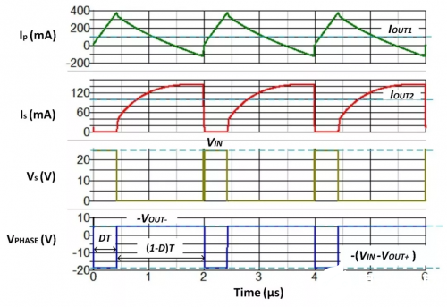
Fig. 2 shows the equivalent circuit of the bipolar power supply using the step-down method during the time interval between DT and (1-D) T. During DT, the upper FET Q1 turns on, causing the reverse voltage bias of the rectifier diode D1, so no current flows in the secondary winding. During (1-D) T, Q1 is off, the current Ip is freewheeling through the lower FET Q2, the voltage (Vs) across the secondary winding corresponds to VOUT +, so D1 is turned on, charging the output capacitor COUT2 and supplying the load . It is recommended to configure the converter with a forced CCM to achieve good voltage regulation of the negative output voltage (VOUT-).

Figure 2. Equivalent circuit of a bipolar power supply using a buck method
The working principle of the SIMPLIS model established using ISL85410 and simulating a bipolar power supply is detailed below. The key parameters are shown in Table 1.

Table 1. Key parameters of bipolar power supply
The simulation waveform is shown in Figure 6. During (1-D) T when Q2 is on, the coupling current of the secondary winding current (Is) causes the total primary current (Ip) to become negative. With proper design, ensure that the negative current is low enough to avoid triggering the negative current limit of the buck regulator under normal operating conditions.

Figure 3. Simulation waveform of a bipolar power supply using a buck method
Figure 1 (b) shows another method that uses an inverting buck-boost conversion to generate a bipolar power supply. In contrast to using buck conversion, inverting buck-boost conversion is to configure the buck regulator IC to invert buck-boost to generate a negative voltage output and use a coupled winding to generate a positive voltage output. Unlike bipolar power supplies that use buck conversion, when the input voltage is lower than the output, the inverting buck-boost conversion can regulate the output (boost conversion). However, in the inverting buck-boost conversion, the FET voltage stress is higher than the buck conversion. Table 2 compares these two conversions and provides design guidance for choosing the best solution for a specific application.
In conclusion
The highly integrated buck regulator IC can more easily achieve different power conversions and meet different application requirements. This article explains how these buck regulator ICs can be used to generate inverting power supplies, bipolar power supplies, and single or multiple isolated power supplies. The highly integrated ISL8541x series buck regulator ICs have a wide input voltage range, integrated start-up diodes and internal compensation. Inverting, bipolar, and isolated power solutions designed with these buck regulator ICs have many important advantages such as a small number of external components, a small overall solution size, and ease of use.
If you want to know more, our website has product specifications for regulators, you can go to ALLICDATA ELECTRONICS LIMITED to get more information

