Do you know switching principle of transistor and base induction voltage?
In a popular metaphor, a transistor is like a faucet. The faucet is divided into three parts: the water supply side (the water supply with constant water pressure), the water side and the switch.
The collector C of NPN transistor is equivalent to the supply side of faucet, the emitter E of PNP transistor is equivalent to the outlet side of faucet, the emitter E of PNP transistor is equivalent to the supply side of faucet, and the collector C is equivalent to the outlet side of faucet. Both NPN and PNP transistor base B is equivalent to the switch of faucet.
Similarly, for the transistor, if "a suitable positive conduction voltage is added to the base of the NPN transistor, the switch between the NPN transistors is turned on, and the current flows from the collector of the NPN transistor to the emitter: if a suitable negative conduction voltage is added to the base of the PNP transistor, the switch between the EC of the PNP transistor is turned on, and the current flows from the emitter of the PNP to the collector.
This is why we often say that NPN transistor is positive voltage on, while PNP transistor is negative voltage conduction. However, because of the incomplete expression, it has brought great negative influence to the readers to understand the conduction principle of the transistor. This is because when discussing the switching principle of transistor, the voltage of NPN transistor from C pole to E pole and PNP transistor from E pole to C pole is often ignored before it is turned on. In other words, the gold key to understand the principle of transistor switch can be found only when it is first realized that there is power supply between the CE (equivalent to the water supply with a certain water pressure on the tap water supply side).
We use the following two experiments to clarify the voltage of the base pole of the transistor at the cut-off time, and propose the concept of "base induction voltage" of the transistor base at the cut-off time, which can be used as a helper to understand the principle of the transistor switch. Only by first defining the specific values of the induced voltage on the base of NPN and PNP transistors, can we really fully and correctly understand why the NPN transistor is high level on and why PNP transistor is low level on.
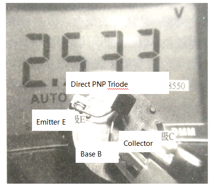
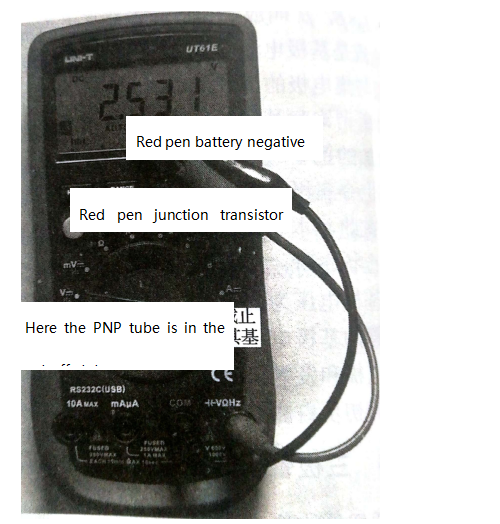
A direct plug-in PNP transistor is used to connect the battery (the CMOS battery slot and CR2030 battery removed from the desktop computer motherboard) to the E pole of the PNP and the negative electrode of the battery to the C pole of the PNP (following the current direction from the E pole to the C pole). The multimeter is placed in the DC voltage file, the red pen is connected to the base of the PNP, and the black pen is connected to the negative electrode of the battery to measure whether the transistor B base has a voltage and what kind of voltage it is.
As shown in figures 1 and 2, the multimeter shows a voltage, and a positive voltage, which is the "base induction voltage" of the PNP transistor.

If you want to know more, our website has product specifications for transistor, you can go to ALLICDATA ELECTRONICS LIMITED to get more information

At this point, the PNP is cut off, and to turn it on, you need to attach a negative conduction voltage to the base B of the PNP. The negative voltage can be obtained by removing the base electrode by resistance from the negative electrode of the ground or battery. This is the essence of PNP transistor low level conduction. The result of introducing negative voltage is that the base voltage of PNP transistor is pulled down, and when the base voltage is pulled down below the threshold voltage when it is turned on, the PNP transistor begins to turn on. Therefore, the complete meaning of PNP transistor low level conduction is that the voltage on its base is low J and its induction voltage is not turned on until its cutoff voltage is turned on. If the base voltage is pulled down to a certain extent (below the threshold voltage, it is not necessary to pull down to 0V), PNP transistor).
Replace the PNP transistor and repeat the experiment using NPN transistor. At this point, the battery positive electrode needs to be connected to the C pole of the NPN, and the battery negative electrode to the E pole of the NPN (following the current direction from the E pole to the C pole). The multimeter is placed in the DC voltage block, the red pen is connected to the base of the NPN, and the black pen is connected to the negative electrode of the battery to measure whether the B base of the transistor has a voltage and what kind of voltage it is. The observation of the multimeter shows that it should remain the same, or the original 0V, of the multimeter, which is the "base induction voltage" of the NPN transistor. At this point, the NPN is cut-off, to turn it on, you need to attach a positive conduction voltage to the base of the NPN. The positive conduction voltage can be obtained by the resistance of the battery or the positive electrode supplied by the battery. This is the essence of NPN transistor high level conduction. The result of introducing positive voltage is that the base voltage of NPN transistor is higher than the induction voltage 0v, at its cutoff time, and the NPN transistor can only be turned on. Therefore, the complete meaning of the high-level conduction of NPN transistor is that the voltage on the base is higher than the induction voltage at its cutoff time before it can be turned on. If the base voltage is pulled up to a fixed degree (above the threshold voltage, that is, about 0.6 ≤ 0.7 V (some are 3V), which is closely related to the specific model, the data table), NPN transistor has been completely turned on.
If a light-emitting diode and a thousand resistance are added to the original experimental device, we can easily use the resistance to add the high level from the positive electrode of the battery to the base pole of NPN or the low level from the negative pole of the battery to the base pole of PNP to control the turn-off of the transistor switch, so as to deepen the understanding of the switching principle of the transistor.
The specific on-voltage of the transistor can be explored through the experimental circuit shown in figure 3. The author strongly recommends that the reader measure it.

R1 is the current limiting resistance, R2 is the isolation resistance, R3 charges / discharge C delay (first close the switch SW1, and then disconnect SW1, closed switch SW2). When the voltage reaches the threshold voltage of the base pole conduction of the transistor, the three nozzles are turned on and the luminous diode is bright. By properly selecting the resistance value of resistor R3 and the capacity of capacitance C, the time from power on to LED can be adjusted and controlled, and the specific conduction voltage of transistor base can be easily measured by using multimeter.

