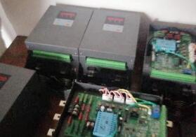
What are the common faults of power regulators?
The load has no output, or the load voltage cannot be increased
1. Check the power supply: the control board and load power supply are normal, and the fast-melting is blown.
2. Check the load: whether the load is open or there is a problem with the wiring.
3. Check the status lights of the control board: green, running state; yellow flashing, shutdown state (no output); red, overcurrent alarm (no output); red flashing, power phase loss (no output); red and green flashing, heat dissipation Over-temperature alarm (no output); steady yellow, control board failure; no light, no power supply or control board failure.
4. Check the input indicator of the control board: green, the brightness should change with the input signal.
5. Check the position of the P1 potentiometer on the control board: adjust clockwise, the output voltage increases.
6. Check the R1 and R2 short-circuit plates of the control board: During automatic control, the R1 and R2 short-circuit plates should be connected.
7. Check the input signal: range, 4 ~ 20mA. Input signal "5.6mA, there should be output. Whether the polarity is reversed.
8. Check the R2 terminal of the control board: R2 outputs 0 ~ 5V (changes with the input signal 4 ~ 20mA).
9. Check the RS terminal of the control board: the RS and GND terminals are short-circuited, the shutdown state (no output), the status light flashes yellow.
10. Check the current limit potentiometer: whether the current limit value is adjusted too low.
Second, the load voltage is abnormal
1. Check the power supply: whether the control board and load power supply are normal. The power supply of the control board should be in phase with the load power supply.
2. Check the load: whether it is running with no load or light load. Transformer load: The secondary side cannot be empty, and must be fully loaded.
3. Manual inspection: If the manual control is normal, it is preliminarily judged that there is no problem with the voltage regulator. Otherwise, connect the dummy load and continue to check.
4. Automatic inspection: When the control input changes by 4 ~ 20mA, the voltage change range of R2 terminal should be 0 ~ 5V.
5. The output voltage can only be adjusted to half of the load power supply: the thyristor module of the voltage regulator damages an arm.
6. Check whether the RC absorber is in bad contact or damaged.

Third, the load voltage is always greater and uncontrolled, the output is always greater, whether it is manual or automatic, it is not adjustable, possible reasons:
1. The load may be open or the load may not be connected
2. The thyristor module of the voltage regulator is damaged due to breakdown. The resistance of the output terminal of the thyristor module is generally greater than 500KΩ
Fourth, start running normally, after a period of time, the output is always greater. Whether it is manual or automatic, it is not adjustable. After shutting down and restarting, it can run normally again. possible reason:
1. The ambient temperature is too high.
2. Long-term load overcurrent.
3. Thermal transient breakdown of the thyristor module caused by instantaneous load overcurrent.
Fifth, connect the dummy load and debug according to the simplest wiring. If the fault location is not easy to judge, the dummy load debugging method can be used. The dummy load is generally 100 ~ 200W bulb.
1. Manual adjustment is normal: preliminary judgment that the voltage regulator is normal, and the load is suspected. Need to check the load power supply voltage, fuse and poor contact, disconnection, short circuit, insulation degradation, discharge and ignition.
2. Manual adjustment is normal and automatic is abnormal: if the control input 4 ~ 20mA current is abnormal, you need to further check the meter; otherwise, you need to check whether the voltage limit of the P1 potentiometer is adjusted too low, and whether the R1 and R2 shorting plates are connected .
3. Manual and automatic adjustment are normal: judge the voltage regulator is no problem.
If you want to know more, our website has product specifications for power regulators, you can go to ALLICDATA ELECTRONICS LIMITED to get more information

