What are the common gate circuits?
1.A phase inverter (non-gate).
The inverter is also called a non-gate, and the output is opposite to the input. The symbol of the inverter is shown in Fig. 3. When A terminal inputs high level, Y terminal outputs low level, and A terminal inputs low power, Y side outputs high level. The common inverter in the motherboard is HCT14,7414, LVCI4,74LVC04, 74 HCT 05, 06 and so on.

(a)Circuit symbol (b)Logical relation
Fig.1 The symbol and Logic relation of Inverter Circuit
2. And gate (AND).
The circuit symbol and logic relation are shown in Fig. 2. A and B are two inputs, Y is the output, A and B have one input is low, Output Y output low level: only A and B input high level, Y output high level.

(a)Circuit symbol (b)Logical relation
Fig.2 Relation between symbol and logic of gate circuit
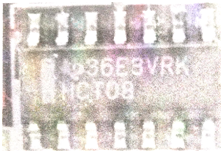
Usually used in the line of VGA interface, field synchronous signal output, signal buffering. HCTO8,74HCT08, LVC08, is common in motherboard and door is also called 08 door. HCTO8 door physical diagram is shown in figure 3.

Fig.3 HCT08 Gate object
3. Non-and-gate (NAND).
The symbol and logic relationship with the common type of HCT132,HCTO3, circuit is shown in figure 4, in which the input end is AZB and the output is Y. If the logic relation between output and input is A and B input low level, Y output is high. When only A and B inputs are all high, Y outputs low levels.

(a)Circuit symbol (b)Logical relation
Fig.4 The relationship between symbol and logic of non-gate circuit
4. Or gate (OR).
Or gates commonly used HCT32, circuit symbols and logic relations as shown in figure 5. One of the input terminals A and B is high, and the output Y is both high, and only when the input A and B input the low power at the same time, the output Y is low.

(a)Circuit symbol (b)Logical relation
Fig.5 Or gate symbols and logic relations
5. A gate circuit consisting of discrete elements.
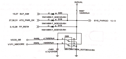
In the main board of AMD chipset, the common diode, MOS transistor composition and gate circuit are used to generate the SYS_PWRGD signal needed for the Nanqiao chip, which indicates that the mainboard power supply is normal, as shown in figure 6.
When the power supply of VIPI_NBCORE bridge is normal, it will be delivered to Q59 through resistance R505, Q59 3 and 4, and 1 to 6. Nanqiao chip sends out 3.3V high level SLP_S3# signal, makes D20 stop. ATX power supply outputs 5V high level ATX_PWR_OK power supply good signal, makes DI8 cut off. The 3.3V high level of the front panel reset switch pin FR_RST# makes the D19 stop. The high level SYS_PWRGD high level of 3VDUAL is pulled over the resistor R497 to the Nanqiao chip, indicating that the main board is supplying normal power. If any of the above signals is low, it will cause the SYS_ PWRGD to be low.

Fig.6 Gate circuit composed of discrete elements
If you want to know more, our website has product specifications for gate circuit, you can go to ALLICDATA ELECTRONICS LIMITED to get more information

