Asus (ASUS) Motherboard Point Bitmap usage method (new version).
1. Introduction to Point Bitmap Viewer.
ASUS from G31 after the motherboard began to abandon the old point bitmap program, use the new version of the point bitmap program PCBRepair Tool as shown in figure 1. The new version of the point bitmap program is more convenient to use and easier to operate than the old version of the point bitmap program.

Fig.1 New version of Point Bitmap Program
2. Point Bitmap View the installation of the program PCBRepair Tool.
Step 1; change the computer system time to 2011.
Step 2, double figure PCBRepairTool_Setup.exe runs the installer, as shown in figure 2.

Fig.2 Installer runs Interface
Step 3, the program installation path defaults, click stall to install, and then prompt the installation as shown in figure 3, and click the OK button. "With the Windows8 system, you need to respecify the installation directory at installation time to install successfully."
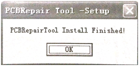
Fig.3 Program installation prompt
Step 4, directly double-click the corresponding motherboard point bitmap sequence source to open the point bitmap. The ASUS P8H67-PRO motherboard peer bitmap when turned on is shown in figure 4.
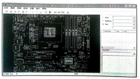
Fig.4 ASUS P8H67-M PRO Motherboard Point Bitmap
3. Description of the Common Toolbar.
The toolbar is at the top of the action window with the corresponding tool buttons, as shown in figure 5.

Fig.5 Toolbar button description
4. Description of the lookup bar.
The lookup bar is located on the right side of the window and is used to find signals, components, and so on. As shown in figure 6, when the RefDes option is selected, and then click the drop-down triangle on the right, the component tag number on the motherboard is displayed. As shown in figure 7, when the Net option is selected, and then click the drop-down triangle on the right, the power supply name on the motherboard is displayed.

Fig.6 RefDes Option diagram Fig.7Net Option diagram
There is a signal lookup bar in the lower-right corner of the window, which outputs the signal you want to find in the input box, and then clicks the Search button on the right to display the corresponding signal, as shown in figure 8.
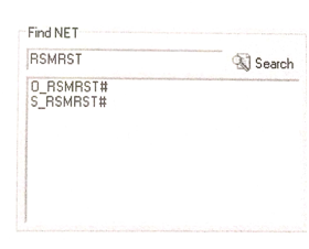
Fig.8 Signal lookup bar diagram
5. Method of finding components.
Take ASUS P8H67-M PRO as an example for component lookup demonstration.
Step 1, double-click the P8167m PRO point bitmap sequence source to open the point bitmap program, as shown in figure 5.
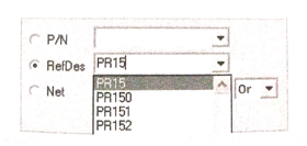
Fig.9 Find column content
Step2, check the RefDes option in the field and output the PR15 resistor position number in the right input box, and the drop-down list displays the components with PR15, as shown in figure 9. Double-click the PR15 on the left window and you see a resistor that turns orange, which is the PR15, and the parameters of the PR15 are displayed in the window below the lookup bar, as shown in figure 10. 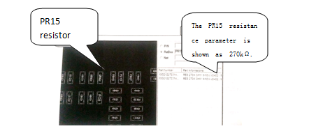
Fig.10 Find PR15 display effect
6. Method for finding signals and connected points.
Take ASUS P8H67-M PRO as an example for demonstration of signal lookup.
Step 1, double-click the P8H67-M PRO point bitmap sequence source to open the point bitmap program, as shown in figure 5.
Step 2, enter the signal you want to find in the signal lookup bar input box in the lower-right corner of the window, and then click the Search button to display the look-up signal, as shown in figure 11.
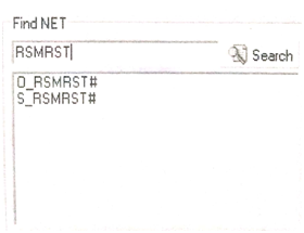
Fig11 Signal lookup demo diagram
Step 3, clicking the corresponding signal name shows the associated connection point of the signal in the window bitmap, and the connected device becomes orange. The mouse wheel is used to zoom in on the corresponding components and the blue one is displayed as the connecting point. At the same time, the feet and parameters of the connected components are displayed at the top of the signal lookup bar, as shown in figure 12.
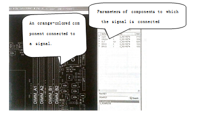
Fig.12 Signal lookup effect graph
Step 4, you need to find a component foot to connect to what components up, just zoom in on the components, and then right-click on the corresponding feet, select the same Net display of the parts. If there are connected components, they will change orange, and the blue ones in the corresponding position will be the connecting points (see figure 1-13).
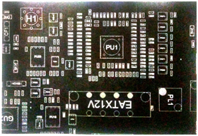
Fig.13 Connected point-effect graph
This article is from Allicdata Electronics Limited. Reprinted need to indicate the source.

