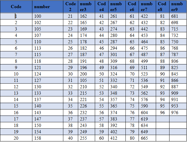
Precision patch resistance and its resistance value.
The resistance value of the Precision chip resistance is shown in Table 1.
Table 1 Precision chip resistance table.


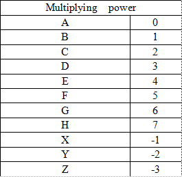
The patch resistance also has another set of resistance coding rule for the identification of the true resistance value of the precision patch resistance. There is no essential difference between the precision patch resistance and the ordinary patch resistance, but the manufacturing error of the resistance value is smaller (1% accuracy).
Precision patch resistance is used in situations where accurate measurement of voltage (current) is needed, and its function is often sampling. Therefore, most of the precision resistance will appear in pairs in the form of voltage distribution network, and the chip will determine its working state according to the sampling value of the precision resistance.
Direct insertion (color ring) resistance and its resistance value.
Direct insertion (color ring) resistance can be divided into two types according to the number of color rings printed on its surface: four-ring resistance and five-ring resistance. The color ring printed on the direct insertion resistance is used to represent the resistance value and error grade of the resistance.
For the four-ring resistance, each of the first three color rings represents a number, which is combined to represent the resistance value. The first two digits represent the effective number of resistance values, the third is the number of zeros to be added, and the fourth digit represents the error level.
For the five-ring resistance, each of the first four color rings also represents one number, which is combined to represent the resistance value. The first three digits represent the effective number of resistance values, the fourth digit is the number of zeros to be added, and the fifth bit table error level.
When the color ring represents the number, the corresponding relationship between the color and the number is as follows: Brown-1, red-2, orange-3, yellow-4, green-5. Blue 6, purple one seven, gray one eight, white one nine, black ten.
When the color ring represents the number of zeros to be added, there may be gold and silver in addition to the ten colors corresponding to 0 9. Gold represents the left shift of the decimal point of the valid number. Silver means that the decimal point of the valid number is moved to the left by two digits.
It is undoubtedly convenient and effective to use color rings to represent the resistance of electric positive. However, the color of the color ring sometimes changes with time, and even difficult to distinguish, which is the disadvantage of the color ring representation.
Readers can download a "color ring resistance calculator" from the Internet.
Measurement of resistance.
Although the resistance is the simplest: the two-terminal component, it is not necessarily possible to accurately measure its true resistance on the first side of the circuit board (not removed). For example, the true resistance of the voltage divider in the voltage distribution network is often inaccurate on one side of the circuit board. Readers must draw this conclusion by comparing the open circuit and the resistance value of the partial voltage resistance in a number of partial voltage networks. This book no longer enumerates the physical diagram.
The investigation of resistance value in partial voltage network should be carried out indirectly. First, the theoretical partial voltage is calculated according to the nominal resistance value, and compared with the actual partial voltage. As long as the actual partial voltage is close enough to the theoretical partial voltage, it can be inferred that the resistance is in good condition (or simply remove the resistance from the circuit board and measure it).
In this paper, the author puts forward the concept of "testability" of components on the side of the board. If a normal element in a circuit can be measured in accordance with its nominal value without removing it, we call it "measured on the road" and vice versa, it is called "untestable on the road". For components that cannot be measured on the road, they can only be removed from the circuit board in order to accurately judge its quality and avoid falling into misunderstandings of maintenance.
If you want to know more, our website has product specifications for precision patch resistance, you can go to ALLICDATA ELECTRONICS LIMITED to get more information

