What is the principle of a Hall effect sensor?
Hall-effect switches and instrument-level sensors are becoming more and more popular in industrial applications, and today product and manufacturing process designers can choose from a variety of highly integrated Hall-effect devices. Although there is still a lot of confusion about what specifications are needed and magnetic field measurements, these devices have proven to be quite easy to apply.
Only the temperature sensor is slightly superior in the number of uses, but the Hall effect sensor has also been used in a wide range of equipment in domestic and commercial applications, including DVDs, CDs, memory drives, automatic toys, mobile phones, car compasses, and car ignition systems . You can also see them in linear, industrial rotating equipment, position detectors, and military / aerospace equipment.
Manufacturing and test engineers use various types of discrete Hall-effect sensors and instruments to provide product information and monitor manufacturing process steps. Although the measurement function may overlap with other types of sensors and instruments, the Hall-effect sensor is obviously the best choice for some types of measurement, and in some cases no other type of test equipment can provide the required Data, including measurements of DC current, rotational position, clearance, surface, or leakage magnetic field. The Hall Effect Sensor History section provides some background on these sensors.
How Hall Effect Sensors Work
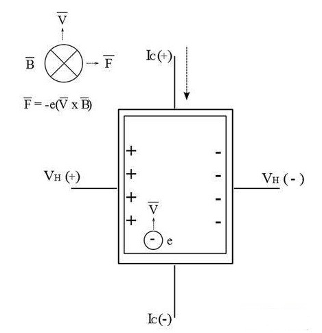
A Hall voltage occurs when a magnetic field passing through a piece of material at an angle affects the current flowing in the material. A Hall plate is usually a rectangular piece of semiconductor material that generates a Hall voltage as an active element or "active area" (Figure 1). Hall plates have a given length l, width w and thickness t.

Figure 1: Hall voltage can be generated and measured with a DC magnetic field.
Measuring Hall voltage
For the magnetic flux vector orthogonal to the Hall plate, the maximum Hall voltage VH is the product of the Hall plate magnetic field sensitivity γB and the magnetic field flux density B, that is:
VH = γBB
This is the maximum Hall voltage that can be measured on a Hall plate. When the surface of the Hall plate and the magnetic flux vector are not orthogonal but at an angle θ, the Hall voltage VH is equal to:
VH = γBB × sinθ
The current I flows through a Hall plate of length l. Current flows between contacts Ic (+) and Ic (-). The magnetic field is in the z direction, that is, orthogonal to the plane of the Hall plate. The force exerted by the magnetic field is called the Lorentz force, and it forces the charge carrier (hole or electron) to move along the illustrated line curve toward the edge of the Hall plate. This force is a coefficient of carrier velocity and magnetic field strength. The Hall voltage finally measured between the contacts VH (+) and VH (-) of a material of width w is proportional to the flux density of the magnetic field.
Instrument configuration
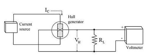
Hall-effect sensor supporting equipment includes a current source for supplying the current Ic and a voltmeter for testing the Hall voltage between the contacts VH (+) and VH (-). Some solutions also use load resistance RL for voltage measurement, as shown in Figure 2. Many types of Hall-effect instruments provide some part of this supporting circuit as an integral part of the measurement system. The voltage leads from the contacts VH (+) and VH (-) can be directly connected to a high resistance voltmeter for reading, or connected to other circuits for amplification, adjustment and processing. (More complex systems using AC sources and lock-in amplifiers are also possible, but are outside the scope of this article.)

Figure 2: Typical configuration of a Hall generator used in the instrument.
application
In industrial environments, Hall-effect devices typically serve one of two main applications:
● Measuring magnetic field strength
● Detection of proximity, position and rotation parameters of moving objects
The following sections discuss each application and provide some tips for using Hall-effect devices efficiently.
Instrument-level sensors for magnetic field measurement
When an industrial application requires accurate or certified magnetic field measurements, instrument-level Hall-effect devices are often used. Some of the more common instrument-level applications include electromagnetic field control, semiconductor ion implantation beam control, acceptance inspection of magnets or magnetic parts, online magnetization confirmation, magnetic field mapping, current detection, and continuous magnetic field exposure monitoring. As an alternative to many of these measurements, a commercial Gauss meter can be used. However, in practical applications, physical or cost constraints often require the use of discrete Hall sensors and commercial electronics.
Instrument-level Hall device users often want accurate values of magnetic fields in a space or void or from a surface. Depending on the measured spatial characteristics, a suitable mounting method is required to place and hold the detection element.
Typical Hall-effect sensors are available in either lateral or axial configurations (Figure 3). Transverse sensors are generally thin, rectangular, and are designed for magnetic circuit gap measurement, surface measurement, and open magnetic field measurement. The axial sensor is generally a cylinder, which is used to measure the center hole of a ring magnet, the magnetic field measurement of a solenoid, the surface magnetic field detection and the common magnetic field detection.

Figure 3: Basic geometry of lateral and axial Hall sensors.
If you want to know more, our website has product specifications for the sensors, you can go to ALLICDATA ELECTRONICS LIMITED to get more information

