How to produce a LED dimming table lamp?
LED dimming table lamp light source changes the traditional incandescent light bulb, using 1W high power and medium φ5mm low power LED hybrid component, dimming circuit is the trigger dimming circuit which has a simple structure plus an op amp. Its actual illumination is no less than 25W incandescent lamp, featuring energy saving, reliability and long service life.
(1) Circuit principle
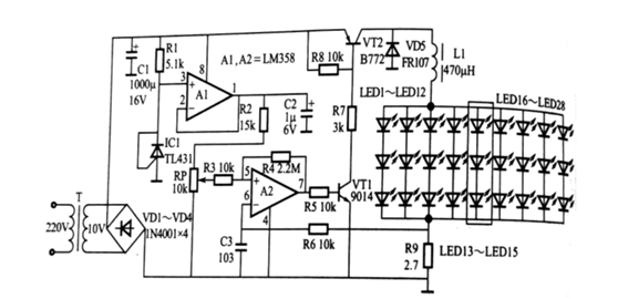
The power supply is taken from the transformer T and the bridge rectifier VD1 ~ VD4 to convert the 220V AC into a DC 14V working power supply. The operational amplifier A1 and the regulator IC1 form a reference voltage for the operational amplifier A2 and the peripheral resistors R3 to R6 to form a non-inverting input reference voltage of the flip-flop circuit, and the inverting input is sampled by the resistor R9.
Compared with the non-inverting input to make the output The end pulse width is adjusted by the reference potentiometer RP, and is amplified by the driving transistor VT1 and the power transistor VT2 to illuminate the LED1 ~ LED28 LED components, and the potentiometer RP can control the current level to complete the actual dimming function. Here, the freewheeling diode VD5 and the energy storage inductor smooth the output current. The schematic diagram of the LED dimming table lamp circuit is shown below.

(2) Component requirements
The power transformer T can be used with a common specification of 8V.A 10V.
LED components LED1 ~ LEDI2 and LED16 ~ LED28 are φ 5mm lamp white light, 12 on each side, a total of 24;
LED13 ~ LED15 is a 1W high power LED, also white light.
The PCB board is made of an aluminum substrate, and a suitable aluminum heat sink is added to increase the heat dissipation effect. The op amps A1 and A2 are dual op amps LM358.
The IC1 regulator is TL431, the regulation voltage is 2.5V, and the remaining resistors and capacitors are conventional.
Inductor L1 is selected to have an outer diameter of φ15mm and a high-frequency magnetic ring can be wound around 40T with a φ0.25mm enameled wire. The current limiting resistor R9 has a power of 1W and a resistance value of 2.2 to 3.0 Ω.
(3) Commissioning
After the power is turned on, the DC voltage of 14V can be measured across the capacitor C1, and it is 10.5V when it is full. The total current of the LED component is determined by R9. The appropriate value is selected to ensure that the operating current flowing through LED13 ~ LED15 is less than 350mA (normally 320 mA), and the working current of each side of φ5mm LED is not more than 20mA, which can be used in LED1~ LED12 and LED16 ~ LED28 are each connected in series with a small 20Ω resistor to keep the working current normal. The 220V input terminal should be equipped with a power switch, and the specifications are optional.
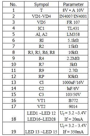
(4) Component parameters are selected as follows:

This article is from Allicdata Electronics Limited. Reprinted need to indicate the source.

