How to make DC adjustable power supply?
Electronic production under amateur conditions, it is very useful to have a voltage regulator with adjustable voltage. For all electronic enthusiasts, practical is the most important. Now introduces an adjustable voltage regulated power supply with an output voltage range of DC 3~12V and a maximum input current of 500mA, which can meet the power supply requirements in amateur production.
(1) Circuit working principle
The schematic diagram of the DC adjustable power supply is shown in Figure 1. The DC adjustable power supply is mainly composed of two main parts: the rectifier circuit and the voltage regulator circuit. The voltage regulator circuit is connected between the rectifier circuit and the load, and the three-terminal adjustable voltage regulator integrated circuit LM317 is used as the main chip, which makes the stability The circuit of the voltage source is very simple.
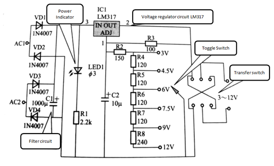
Figure 1 DC adjustable power supply schematic
Before introducing the working principle of the DC adjustable power supply circuit, the working principle of the three-terminal adjustable voltage regulator integrated circuit LM317 is introduced. The typical application circuit is shown in Figure 2.
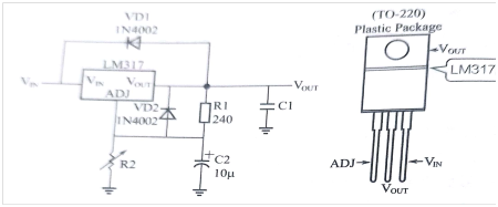
Figure 2 typical application circuit
The relationship between its output voltage and resistance is:

It can be known from the formula that when the resistance of R2 is changed, different output voltage values can be obtained.
After the AC 220V is stepped down by the power transformer, the output voltage is about 14V. After rectification and filtering, the LED is illuminated as the power indicator. Adding the DC voltage of the filtered output DC17V to the input end of the three-terminal regulator integrated circuit, adjusting the resistance of the controlled resistor, the ground voltage value of the ADJ of the LM317 control terminal can be changed, thereby obtaining different voltage outputs at the output end. By adjusting the voltage value of the ADJ of the LM317 control terminal, the output terminal can output different voltage values, thereby achieving an adjustable regulated output. At the output end, the regulated power supply is also connected with a polarity switching output switch. By selecting, the input terminal can obtain positive and negative opposite voltage polarities.
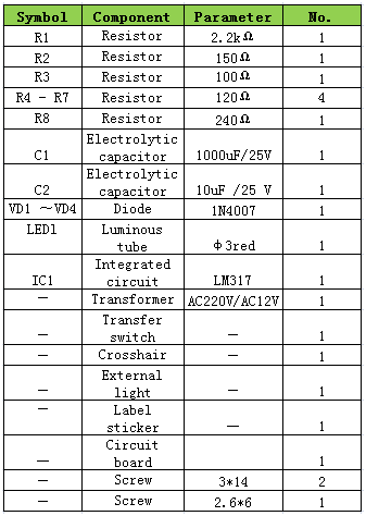
(2) DC adjustable power supply components list.
The list of DC adjustable power supply components is shown below.
(3) Installation and commissioning
Firstly, all the components are soldered to the printed board as required. Pay attention to the welding sequence and the welding time to prevent damage to the components, as long as the welding is correct. In particular, the welding of the three-terminal regulator IC LM317 cannot reverse the direction.
At the same time, since the outer casing of the product is made of plastic material, it is necessary to master the technique when welding the lead wire of the transformer power terminal. First, the copper piece of the plug is scraped off with a knife, and then the scraped copper piece is tinned with a flux such as rosin. The time should be short, otherwise it is easy to melt the plastic. After the copper piece of good tin is cooled, the welding of the transformer leads is performed.
Since the space of the box is relatively small, when installing large-volume components, the three-terminal regulator LM317 should be placed obliquely when it is installed, so that its highest point protrudes out of the protruding space under the transformer. The 1000μF filter capacitor is large in volume. It should be soldered to the soldering surface of the circuit board (copper foil surface), that is, it should be mounted facing away from other components (others are inserted on the silk screen surface), and then placed horizontally after soldering, otherwise the box will not be covered, and the component layout and installation will be The physical map after installation and debugging is shown in Figure 3 and Figure 4.
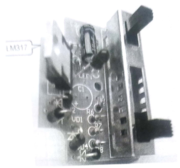
Figure 3: Front side of the board component of the soldered component
Note: Since the LM317 is relatively high, the actual layout needs to be laid out according to the angle of Figure 3, otherwise it is easy to withstand the plastic casing.
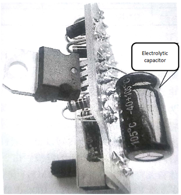
Figure 4 filter capacitor installation
Install the transformer and circuit board in the F plastic box and connect the input/output leads of the transformer. The power indicator LED is punched out and fixed from the hole of the housing, and the DC adjustable power supply is completed, as shown in Figure 5.
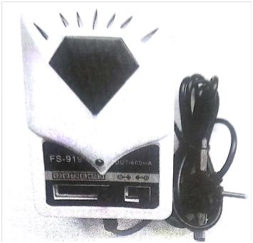
Figure 5
This article is from Allicdata Electronics Limited which offer electronic components, semiconductors, antennas, capacitors, connectors, diodes, transistors, IC,resistors,etc.
For more product information, please go to the website to get it.
Reprinted need to indicate the source.

