How to manufacture a mobile phone battery charger?
The design adopts discrete component design, power supply of switching power supply, moderate number of electronic components, and has the advantages of high manufacturing success rate, reliable circuit, small size, light weight and high efficiency.
The power supply part circuit has the characteristics of typical switching power supply, and the circuit is simple, the principle is clear, and the utility model has high practicability, and can charge the lithium ion mobile phone battery with the charging capacity of 250 ~ 3000 mA. The battery is in different states and has different color indicators for display, which is very intuitive. An automatic identification line is built in to automatically identify the battery polarity. The output voltage is 4.2V, which can automatically adjust the output current to make the battery reach the optimal state of charge and extend the battery life.
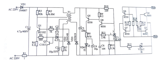
1.Mobile phone battery charger circuit working principle , as shown in.

Figure 1
2 Mobile phone battery charger material parameters as shown below

Figure 2
3. Installation precautions
1) Because the circuit design size is relatively small, most of the components are installed horizontally. The manufacturer must pay attention to the component position when installing the components. The components should be shaped first, and the shaped components should be inserted into the circuit board. After soldering, The component pins can be trimmed.
2) When installing diodes, triodes and electrolytic capacitors, be sure to pay attention to the polarity. If the identification on the circuit board is not known, check the schematic diagram carefully to determine what components can be installed. Otherwise, the reverse of the components will make the circuit not work properly.
3) When the charging electrode is soldered to the lead wire, the oxide layer on the electrode is scraped off with a blade before soldering. The solder should not be too much during soldering. The soldering time should not be too long. Since the outer casing is a plastic part, the temperature will be too high to melt the plastic and cause deformation. After welding, press the front clip spring by hand to try to move flexibly.
4) The two-color LED has three pins, the middle pin is the common end, and the two legs correspond to the red and blue anodes respectively. If the installation direction cannot be determined during soldering, you can first test which pin is blue light with the digital tube's pole tube block, and then the solder joint of the blue pin and R13 is soldered, and the installation direction of the two-color tube can be accurately determined. Since the electrical parameters of the two-color tube are different, the reverse installation will make the charger unable to function normally work. After installing, connected to the power board, there is no red light flashing when the power is not plugged in, indicating that the direction of the two-color tube is reversed, the two-color tube can be removed for another direction and reinstalled and tested.
5) Since the 220v introduction pin and the circuit board are connected through the plug pole piece.
If the installation is in poor contact, the charger will not work properly. When the board is soldered, it must be tinned on the circuit board on which the electrode is mounted (there are several copper wires on the circuit board without the solder resist layer).
Before inserting the housing, loosen the pin fixing screws, then place the circuit board flat into the housing, and then tighten the fixing screws. After this step is completed, use a multimeter to block the contact between the measuring pins and the circuit board. If the resistance is infinite, it should be carefully adjusted.
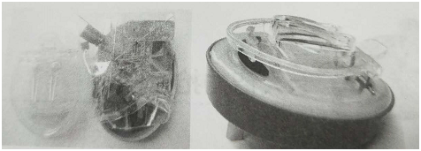
The appearance of the mobile phone battery charger is shown in Figure 2.

Figure 2
4. Function debugging
1) After all components have been installed, they should be carefully checked to confirm that the components are installed correctly and then can be energized.
2) Since this circuit uses AC 220V power supply, from the perspective of safety, the DC power supply can be used to debug the charging circuit during debugging. The method is as follows.
3) Prepare an adjustable DC stabilized power supply with an output current of not less than 1A, disconnect one pin of VD3 from the circuit board, and then adjust the DC regulated power supply to output 5.6V, which is connected to both ends of CS. When you can see the blue indicator light, take a mobile phone board, adjust the charging electrode lead spacing to exactly the distance between the positive and negative poles on the board, loosen the charging clip, put the board into it, if the board The battery is not enough. You can see that the red light is shining. If these rules are met, the charging circuit is basically normal.
4) All components are fully assembled and connected to 220V for testing. Note that at this time, do not touch the components of the switching power supply, otherwise it is prone to electric shock. Use a multimeter to measure the voltage across C5. Normally it should be between 5.6 and 6V (the actual voltage value is slightly different due to different component parameters). Measuring the voltage between the charging electrodes should be about 4.3V, the polarity is random. When connected to the electric board, the voltage between C5 is between 5.2 ~ 5.5V, and the voltage between the charging electrodes is the voltage value across the board. .
5) Install the mobile phone battery that needs to be charged, the blue indicator light is on, and plug it into the household 220V socket. At this time, you can see that the blue light is always on and the red light is shining, which means the charger is charging the battery.
When the power of the board is sufficient, the red light stops flashing and the blue light is always on. If the whole process meets the above rules, it can be judged that the charger works normally.
This article is from Allicdata Electronics Limited. Reprinted need to indicate the source.

