What is the work principle of LED cycle light and the list of components to form it?
The transistor multivibrator is a rectangular pulse generating circuit. This circuit can generate a rectangular pulse with a fixed frequency and a certain width without using an external trigger signal, and is often used as a pulse signal source. Since the rectangular wave is rich in multiple harmonics, it is called a multivibrator. When the multivibrator is working, the output of the circuit is constantly flipped between high and low levels, and there is no stable state, so it is also called an unsteady trigger. The schematic diagram of the LED cycle light is shown in Figure 1.

Figure 1 LED cycle light schematic
(1) Circuit working principle
The LED cycle light is a cycle light consisting of 3 pcs transistors and 9 pcs LEDs. When the power is turned on, the three transistors will be rushed to conduct, but due to the difference in components (the transistor conduction time is different), only one of the transistors is turned on first. If the transistor Q1 is turned on first, the collector voltage of the transistor Q1 drops, so that the left end of the capacitor C1 approaches zero voltage. Since the voltage across the capacitor does not change abruptly, the base of transistor Q2 is also pulled to approximately zero voltage, causing transistor Q2 to turn off.
The collector of the transistor Q2 is high voltage, then the LED connected to the collector of the transistor Q2 is illuminated. At this moment, the high voltage on the collector of the transistor Q2 is increased by the capacitor C2, and the voltage of the base of the transistor Q3 is raised, and the transistor Q3 will also be turned on quickly.
Therefore, during this period of time, the collectors of the transistor Q1 and the transistor Q3 are both low voltage, and only the LED connected to the collector of the transistor Q2 is bright, and the other two transistors are not bright. As the power supply charges C1 through the resistor R3, the base voltage of the transistor Q2 is gradually increased. When the voltage exceeds 0.6V, the transistor Q2 changes from the off state to the on state, the collector voltage of the transistor Q2 decreases, and the LED is extinguished. At the same time, the drop in the collector voltage of the transistor Q2 is caused by the action of the capacitor C2 to lower the base voltage of the transistor Q3, and the transistor Q3 is turned off by conduction. The LED connected to the collector of transistor Q3 is lit. In this cycle, the three transistors in the circuit are turned on and off in turn, and the three LEDs continuously illuminate. Changing the capacity of the capacitor can change the speed of the cycle light cycle. The working voltage of the circuit is DC 3~9V, which can be powered by battery or external DC power supply.
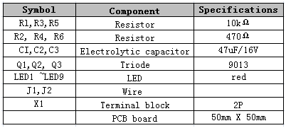
(2) List of components

LED cycle light component list
This article is from Allicdata Electronics Limited. Reprinted need to indicate the source.

